Boiler Feed Pump Calculation: The Comprehensive Hydraulic Sizing Handbook
A rigorous engineering treatise on computing boiler feedwater mass flow, IAPWS-IF97 volumetric thermal expansion, Total Dynamic Head (TDH), NPSHa cavitation margins, and electric motor sizing.
Need to compute your system immediately?
Use our live interactive suite to evaluate Q_design, TDH, and NPSH margins with custom fluid properties.
Handbook Contents
- Thermodynamic Fundamentals of Boiler Feedwater Injection
- Derivation 1: Mass Flow & Volumetric Conversion (IAPWS-IF97)
- Derivation 2: Total Dynamic Head (TDH) & Darcy-Weisbach Losses
- Derivation 3: Net Positive Suction Head Available (NPSHa)
- Derivation 4: Hydraulic Horsepower, Shaft BHP & Motor Sizing
- Industrial Worked Example: 45 Ton/Hour Watertube Boiler
- Frequently Asked Questions (FAQ)
1. Thermodynamic Fundamentals of Boiler Feedwater Injection
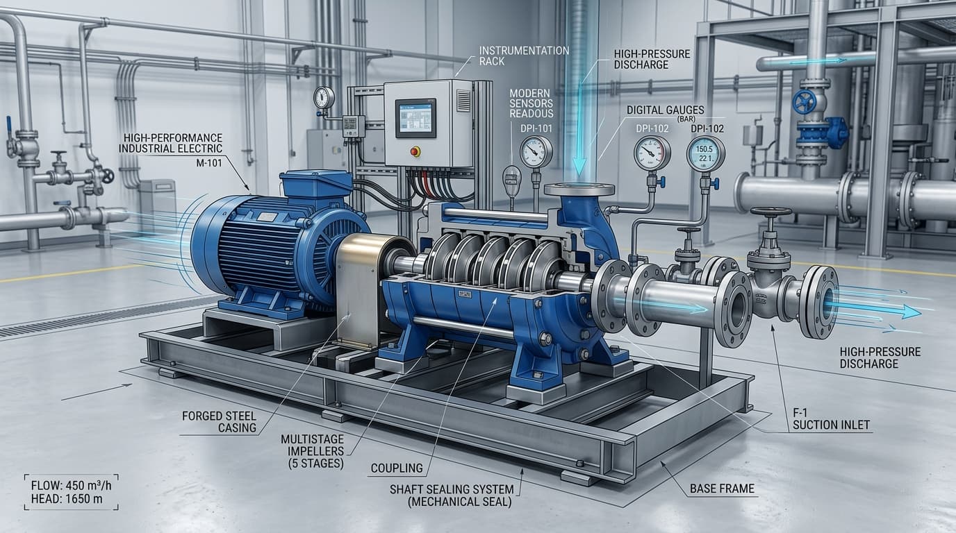
In steam Rankine power cycles and industrial process heating systems, the boiler feed pump is arguably the single most demanding rotating machine in the facility. Operating in series between a low-pressure deaerator storage tank and a high-pressure steam drum or once-through evaporator coil, the feed pump must continuously deliver subcooled water across pressure differentials that commonly exceed 100 bar (1,450 psi).
Failure to accurately size a boiler feed pump has severe operational consequences. An undersized pump cannot maintain the boiler water level during rapid steam load transients, triggering low-water trip sequences that shut down entire production lines. Conversely, an oversized pump forces the unit to operate far to the left of its Best Efficiency Point (BEP), dissipating massive hydraulic horsepower into recirculation heat, inducing destructive suction eye cavitation, and driving excessive wear on mechanical seals and balance drums.
2. Derivation 1: Mass Flow & Volumetric Conversion (IAPWS-IF97)
Feedwater mass flow differs fundamentally from rated boiler steaming capacity due to surface blowdown and system leakages. Continuous blowdown is necessary to remove dissolved silica, chlorides, and suspended solids concentrated by the evaporation process.
Where:
- M_feed: Continuous required feedwater mass flow rate (kg/h or lb/h).
- M_steam: Boiler Maximum Continuous Rating (MCR) steam output (kg/h or lb/h).
- X_blowdown: Continuous surface blowdown rate (typically 2% to 6%).
To convert mass flow into operating volumetric displacement ($Q_{operating}$), the engineer must employ true fluid density derived from international thermodynamic formulations (IAPWS-IF97). Because feedwater drawn from pressurized deaerators exists at 105°C to 160°C, liquid density drops markedly:
Q_design = Q_operating × S_flow
ASME BPVC Section I mandates a safety margin ($S_{flow}$) between 15% and 25% (multiplier 1.15 to 1.25) to accommodate sudden boiler drum swell and rapid firing response.
3. Derivation 2: Total Dynamic Head (TDH) & Darcy-Weisbach Losses
Centrifugal pumps do not generate pressure directly; they impart kinetic velocity that converts into static liquid column height (Head). Total Dynamic Head (TDH) defines the total energy per unit weight that the machine must transfer to the fluid:
TDH = [ (P_drum_g - P_suction_g) / (ρ × g) ] + (Z_drum - Z_tank) + Σ h_friction
The static head term represents the net vertical elevation difference between the deaerator liquid surface and the boiler drum inlet nozzle. When the deaerator is elevated high above the pump centerline (positive flooded suction), it reduces the static work required by the pump.
Discharge friction losses ($\Sigma h_{friction}$) must account for three primary pressure drops:
- High-Pressure Economizer: Typically induces 1.5 to 3.5 bar (20 to 50 psi) of frictional resistance across finned tube banks.
- Modulating Feedwater Control Valve (FCV): Requires a minimum 2.0 to 4.0 bar differential across its trim to maintain precise authority over drum water level.
- Safety Valve Overpressure Cushion: ASME codes require designing against 103% to 105% of maximum drum design pressure to guarantee feedwater delivery during peak pop pressure scenarios.
4. Derivation 3: Net Positive Suction Head Available (NPSHa)
Cavitation is the most destructive physical phenomenon affecting boiler feed pumps. When local static pressure falls below the fluid’s saturation vapor pressure, vapor cavities form instantly. As these bubbles travel into higher pressure regions within the impeller vane passages, they collapse with violent microjet velocities exceeding 1,000 m/s, generating localized shock pressures up to 10,000 bar.
The Saturated Deaerator Paradox: In deaerated feedwater systems, the water in the storage vessel is at its exact boiling point. Thus, $P_{suction\_abs} = P_{vapor}$. The pressure term cancels out completely:
Consequently, the only driving head available to prevent cavitation flashing is the vertical static height of the deaerator water column above the pump impeller centerline minus friction losses in the suction line. Per Hydraulic Institute (ANSI/HI 9.6.1), the NPSHa margin must satisfy:
5. Derivation 4: Hydraulic Horsepower, Shaft BHP & Motor Sizing
Hydraulic power transferred to the fluid is computed from the mass flow and head:
P_shaft (BHP) = P_hydraulic / η_pump
P_motor = P_shaft × S_motor
Industrial centrifugal boiler feed pumps operate with hydraulic efficiencies ($\eta_{pump}$) between 68% and 82%. Commercial electric motors (per IEC 60034 or NEMA MG-1) must include non-overloading margins ($S_{motor}$ between 1.10 and 1.15) to prevent thermal overload trips during cold plant startups.
6. Industrial Worked Example: 45 Ton/Hour Watertube Boiler
Design Parameters:
- Boiler Steam Rate ($M_{steam}$): 45,000 kg/h
- Drum Operating Pressure ($P_{drum}$): 42.0 bar(g)
- Continuous Blowdown ($X_{blowdown}$): 3.5%
- Deaerator Temperature: 130°C (ρ = 934.8 kg/m³, P_vapor = 2.70 bar abs)
- Deaerator Elevation (Z_suction): 8.0 m above pump centerline
- Boiler Drum Inlet Elevation (Z_drum): 18.0 m above pump centerline
- Suction Line Losses ($h_{f\_suction}$): 0.5 m
- Discharge Friction Losses (Piping + Economizer + FCV): 4.5 bar (49.1 m)
- Pump Efficiency ($\eta_{pump}$): 74%
- Manufacturer NPSHr: 3.8 m
Calculation Trail:
7. Frequently Asked Questions (FAQ)
How does continuous boiler blowdown alter pump flow sizing?
Boilers require continuous surface blowdown (typically 2% to 7% of steaming rate depending on makeup water silica and conductivity limits) to prevent TDS scaling on heat-transfer surfaces. The pump mass flow must satisfy M_feed = M_steam × [1 + (X_blowdown / 100)], ensuring steady drum water level is maintained during full blowdown rates.
Why does assuming water density of 1,000 kg/m³ create dangerous undersizing?
Feedwater drawn from pressurized deaerators is hot, typically 105°C to 160°C. Under these conditions, thermal expansion lowers water density to ~910–955 kg/m³. If an engineer assumes 1,000 kg/m³, the calculated volumetric displacement (m³/h or GPM) will be underestimated by 5% to 10%, causing the pump to run off-curve at end-of-curve flow where motor overload and cavitation occur.
What is the standard ASME safety margin for boiler feed pump discharge pressure?
Per ASME Boiler and Pressure Vessel Code (BPVC) Section I, the boiler feed pump must supply feedwater at a pressure sufficient to overcome the highest safety valve setpoint plus full piping friction, economizer drop, and feed regulating valve drop. A minimum 5% to 10% head margin above drum operating pressure is standard practice to prevent backflow during transient steam demand spikes.
Why does deaerator saturation eliminate pressure head in NPSHa calculations?
Because the deaerator vessel operates at boiling equilibrium where liquid surface pressure equals saturation vapor pressure (P_suction = P_vapor), the term (P_suction - P_vapor) / (ρ × g) equals zero. The net positive suction head available is therefore purely dependent on the static vertical liquid elevation above the pump impeller centerline minus suction friction losses.
What is Minimum Continuous Stable Flow (MCSF) and why is an Automatic Recirculation Valve (ARV) required?
At low boiler steam demand (such as plant startup or hot standby), a feed pump operating near shutoff head dissipates mechanical shaft energy into fluid heat. Within seconds, fluid temperature exceeds saturation temperature, causing explosive internal vaporization and bearing seizure. An ARV automatically bypasses a minimum stable flow (typically 20% to 35% of BEP flow) back to the deaerator.
Explore Related Engineering Guides
Read our dedicated publications on deaerator storage volume sizing and anti-cavitation diagnostics.