Boiler Feed Pump Cavitation Diagnostics & NPSHa Verification
An in-depth mechanical and fluid dynamics guide to identifying acoustic cavitation signatures, calculating true NPSH margins under saturated deaerator conditions, and designing anti-flashing suction piping.
Check your pump suction velocity and NPSH margin
Calculate pipe velocity, velocity head, and NPSHa margin against manufacturer NPSHr.
1. The Physics of High-Temperature Feedwater Cavitation
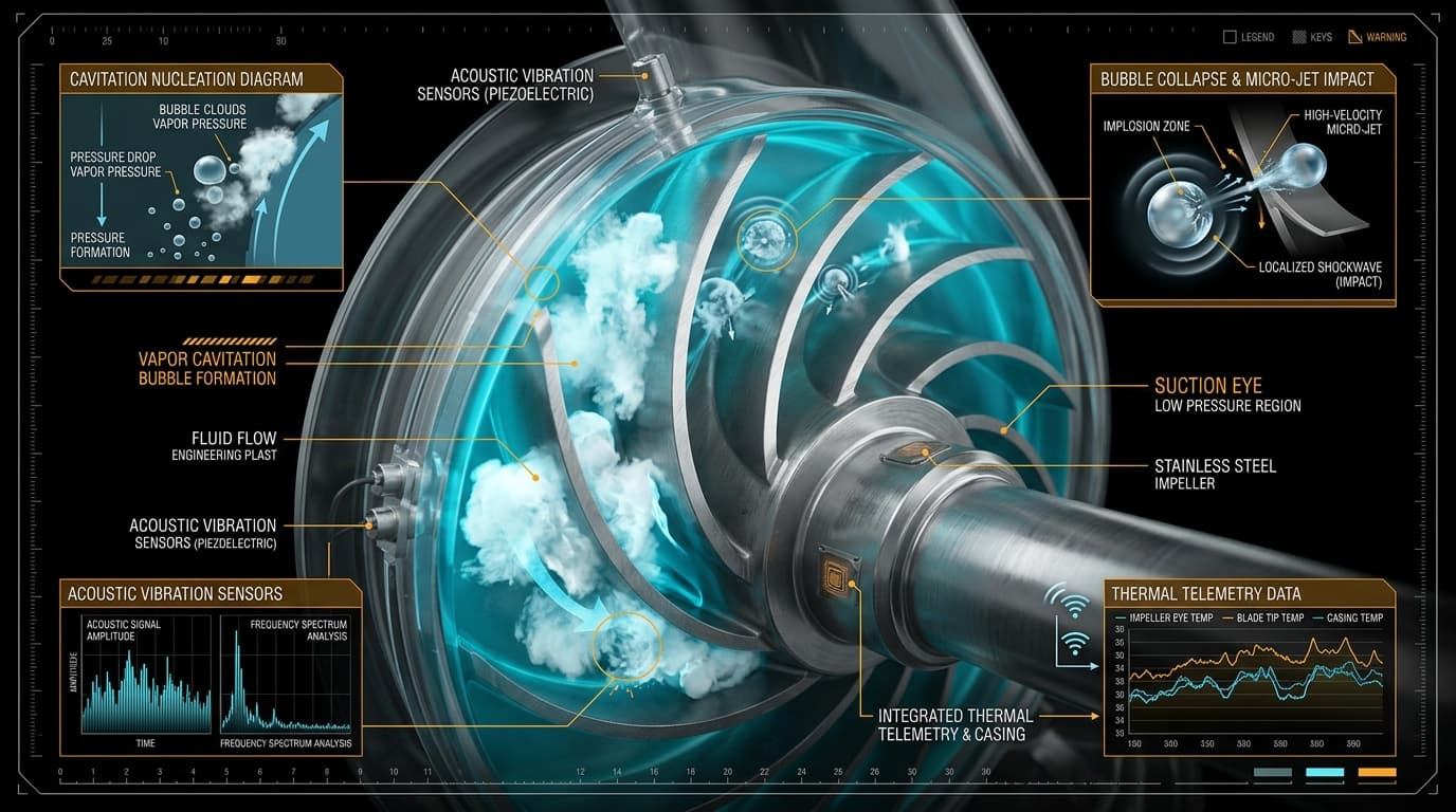
Cavitation in boiler feed pump applications differs fundamentally from cold-water municipal pumping. Because feedwater drawn from deaerator vessels exists at temperatures ranging from 105°C to 160°C (221°F to 320°F), even a slight local pressure drop of just 0.1 bar triggers explosive flashing.
When saturated feedwater flows into the low-pressure suction eye of the first-stage impeller, fluid acceleration produces a local drop in static pressure per Bernoulli's principle:
If $P_{local} < P_{vapor}(T)$, micro-bubbles form along the leading edges of the impeller vanes. When these cavities travel inward toward higher pressure zones between the vanes, they implode asymmetrically. The resulting liquid microjets impact the metal surface at speeds reaching 1,200 m/s, rapidly eroding 13% Chrome stainless steel impellers within hundreds of operating hours.
2. Saturated Suction Dynamics: The Zero-Pressure-Margin Reality
The standard definition of Net Positive Suction Head Available is:
Because the deaerator operates as a direct-contact steam condenser where steam and water are at thermodynamic boiling saturation, $P_{suction\_abs}$ and $P_{vapor}$ are identical. Therefore, the pressure head term is zero:
This fundamental physical reality means:
- Raising deaerator steam operating pressure does NOT increase NPSHa, because water vapor pressure rises in lockstep.
- The vertical elevation of the deaerator vessel ($Z_{suction}$) is the ONLY steady-state variable available to provide positive driving margin.
- Friction losses in the suction downcomer must be minimized through oversized pipe diameters and smooth-radius long-radius elbows.
3. Transient Deaerator Depressurization & Sudden Flashing
The most dangerous operational regime for boiler feed pumps occurs during sudden load rejections or boiler trips. Under normal operation, the deaerator is supplied with extraction steam from a turbine or auxiliary steam header.
When a turbine trips, extraction steam supply halts instantly. The steam vapor space inside the deaerator vessel condenses rapidly, causing vessel pressure to collapse within seconds. However, the water in the vertical suction downcomer pipe possesses considerable thermal mass; it remains at its pre-trip elevated temperature.
Because the water in the downcomer is hotter than the saturation temperature corresponding to the newly dropped vessel pressure, the entire liquid column flashes violently into steam inside the pipe before reaching the pump. This starvation leads to instant seizure of close-clearance wear rings, shaft deflection, and catastrophic mechanical seal failure.
4. Best Practice Suction Piping Guidelines (HI 9.6.1 & API 610)
To safeguard against both steady-state and transient cavitation, industrial piping standards mandate strict layout rules:
5. Frequently Asked Questions (FAQ)
What causes cavitation in boiler feed pumps even when the tank is elevated?
The primary cause is transient deaerator pressure decay following sudden turbine trips or boiler firing cuts. When steam supply to the deaerator drops rapidly, vessel pressure falls faster than the bulk liquid can cool. High-temperature water in the downcomer flashes into steam bubbles prior to entering the impeller eye, causing severe flashing cavitation despite static elevation.
What is the recommended suction line velocity for boiler feed pumps?
Per Hydraulic Institute (HI 9.6.1) and API 610 guidelines, boiler feed pump suction piping velocity should be strictly restricted to 0.8 to 1.5 m/s (2.5 to 5.0 ft/s). Keeping velocity low minimizes Darcy-Weisbach friction head losses and dampens acoustic turbulence.
How do you differentiate between acoustic cavitation and mechanical unbalance?
Acoustic cavitation emits high-frequency broad-band crackling noise resembling gravel passing through the pump casing, typically measured in high-frequency vibration spectra (5 kHz to 20 kHz). In contrast, mechanical unbalance manifests as discrete 1X running frequency peaks on accelerometer spectral readouts.
Explore Full Mathematical Proofs
Review governing formulations for Darcy-Weisbach friction loss and brake horsepower calculations.